Helical Electrodes for Electrophysiology in Wild Animals
Typically, electrodes (and electrode leads) are made of a single piece of solid wire. Geddes & Roeder highlight the wide use of different anticorrosive, biocompatible metals and alloys (e.g., stainless steel, silver, nichrome) used in electrophysiology. Solid wire has the advantage of low resistivity but suffers in situations where electrodes are not fully encapsulated (like in dental cement) and require routing due to their tendency to sheer when bent only a few times. A multi-strand cable is not an ideal solution either because it can still sheer, the small internal wires have poorer electrical qualities, and the air gaps between wires can wick, collect, and hold fluid which also effects performance.
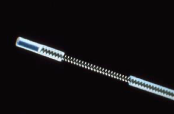
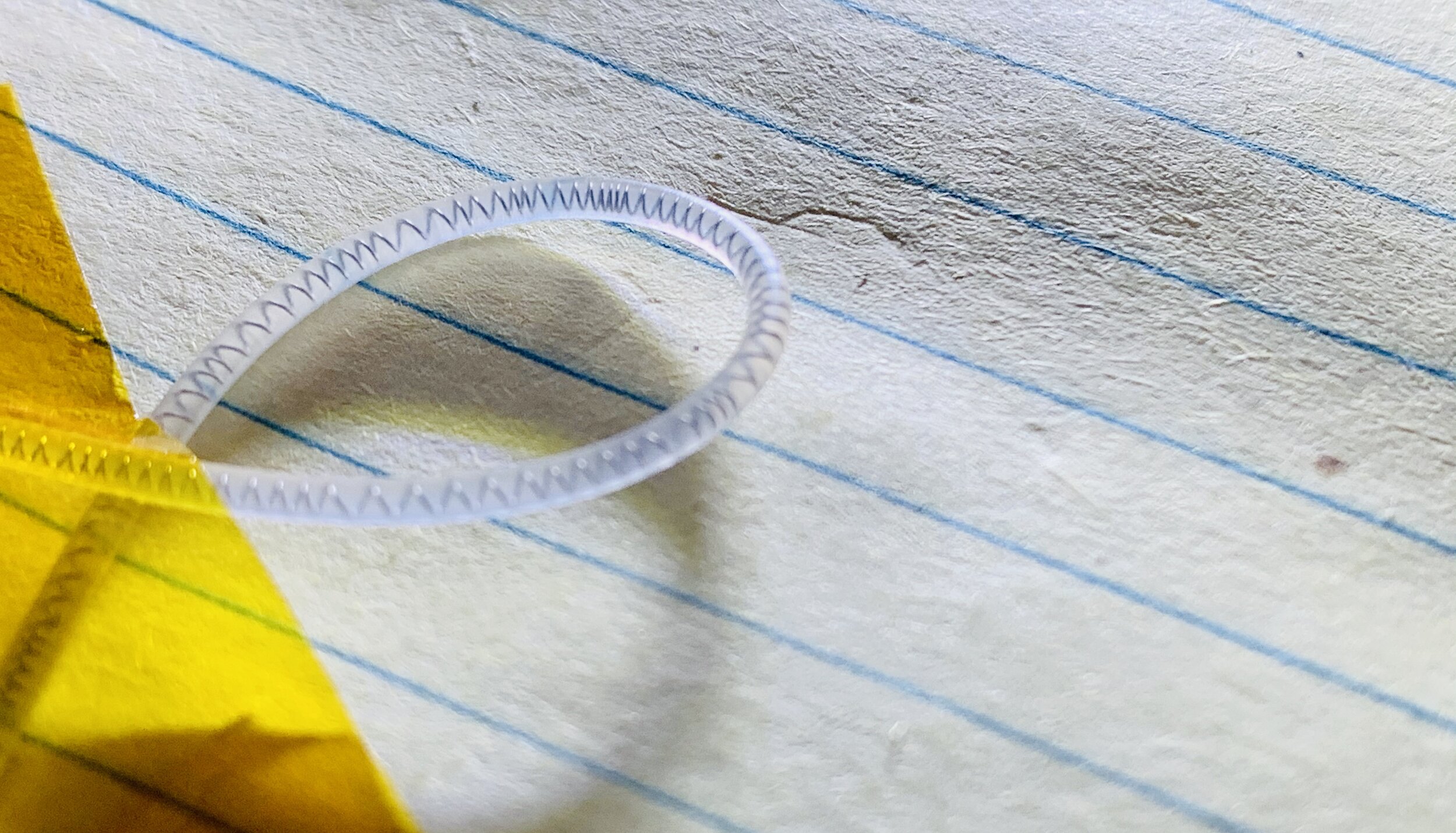
DSI helical leads for small rodent applications.
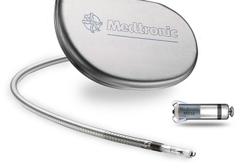
Medtronic helical leads for human applications.
One solution to this problem is to use helical electrodes, which are common to pacemakers and deep brain stimulators since those electrodes undergo substantial routing. This has been adopted by small animal physiologists and can be seen in Data Sciences International (DSI) documentation. Open Source Instruments has done an immense amount of work on developing and testing flexible electrodes (that you can buy), leveraging spring manufacturers, which is quite clever. In applications where electrodes are being routed or weaved—especially if the animal will undergo full recovery and resume normal behavior (like in a wild or free-ranging animal)—lead flexibility is going to be critical to the endurance and quality of the electrophysiological recordings.
Building Helical Electrodes
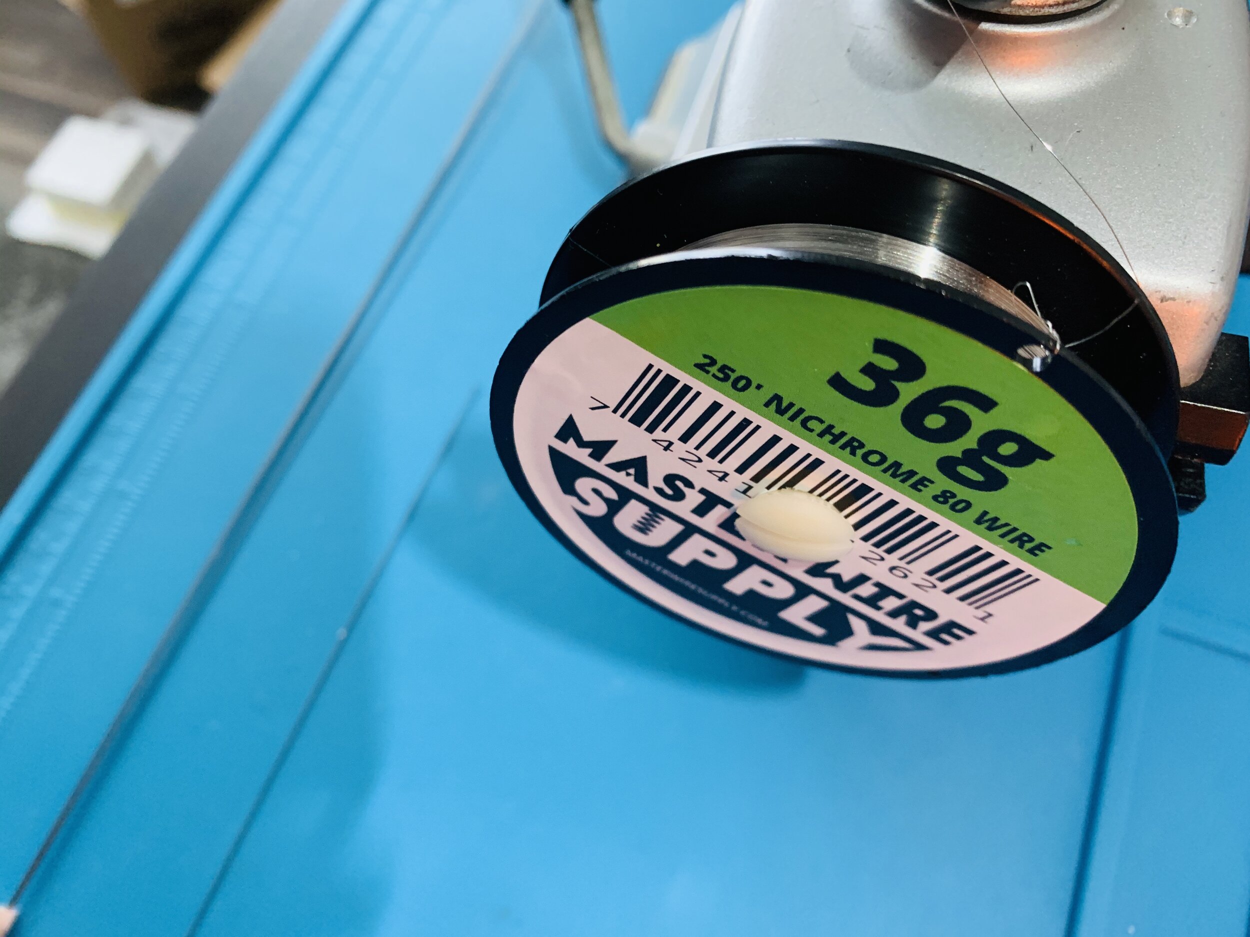
I happened to have some nichrome sitting around (from Amazon) and wondered if these electrodes could be easily built.

-
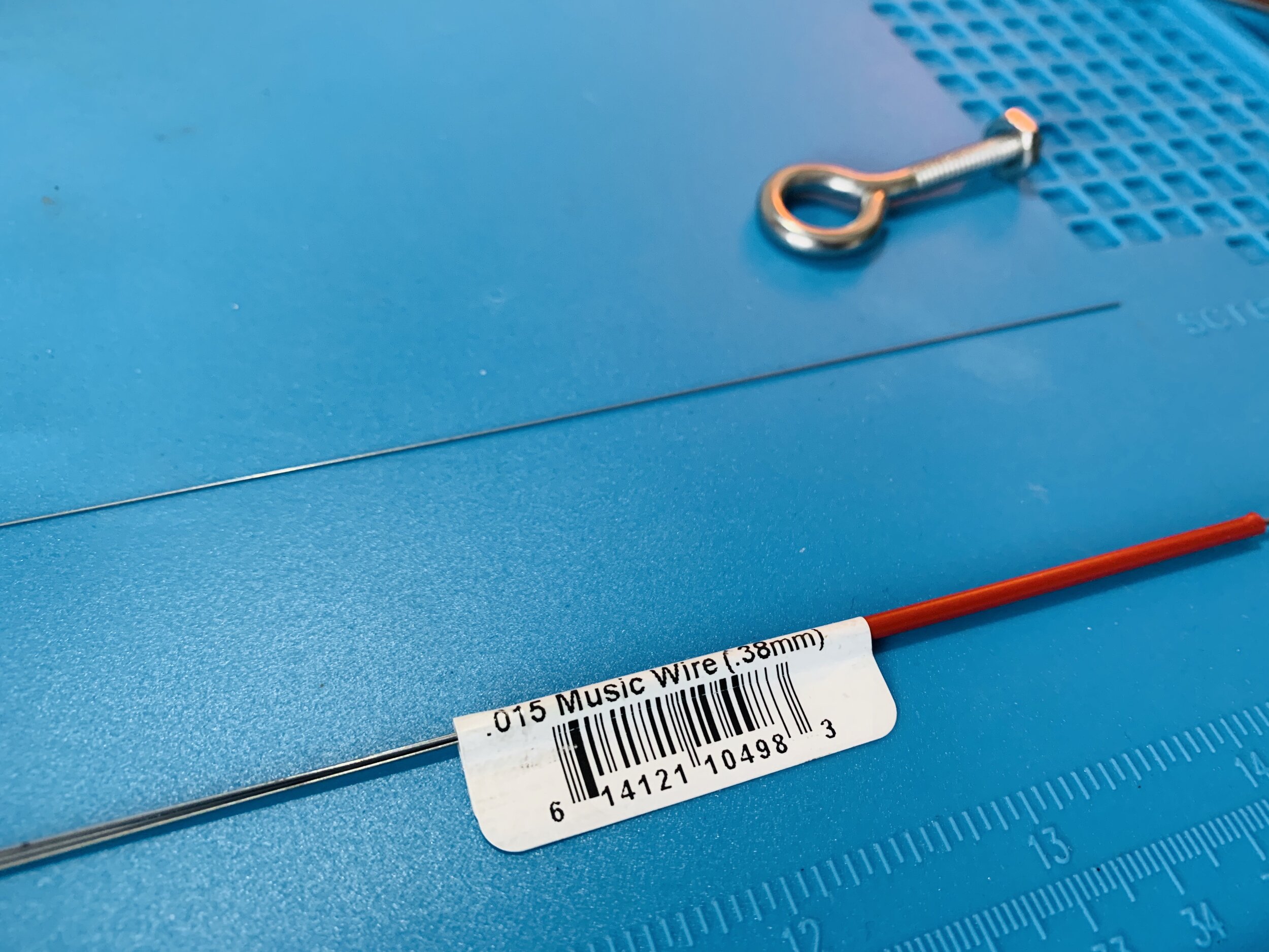
I used 36 gauge (0.005in, 0.127mm) nichrome 80 wire as the electrode and 0.38mm (0.015”) steel music wire as the wrapping “core”.
-
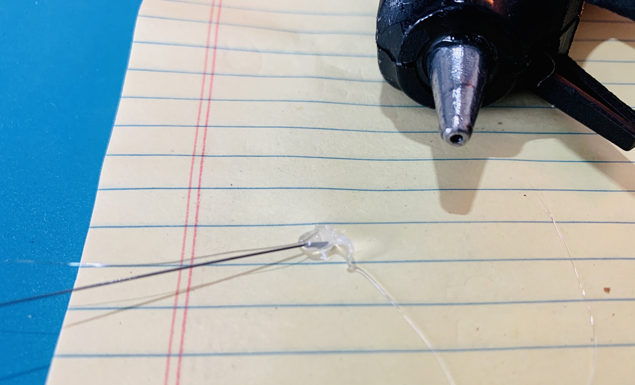
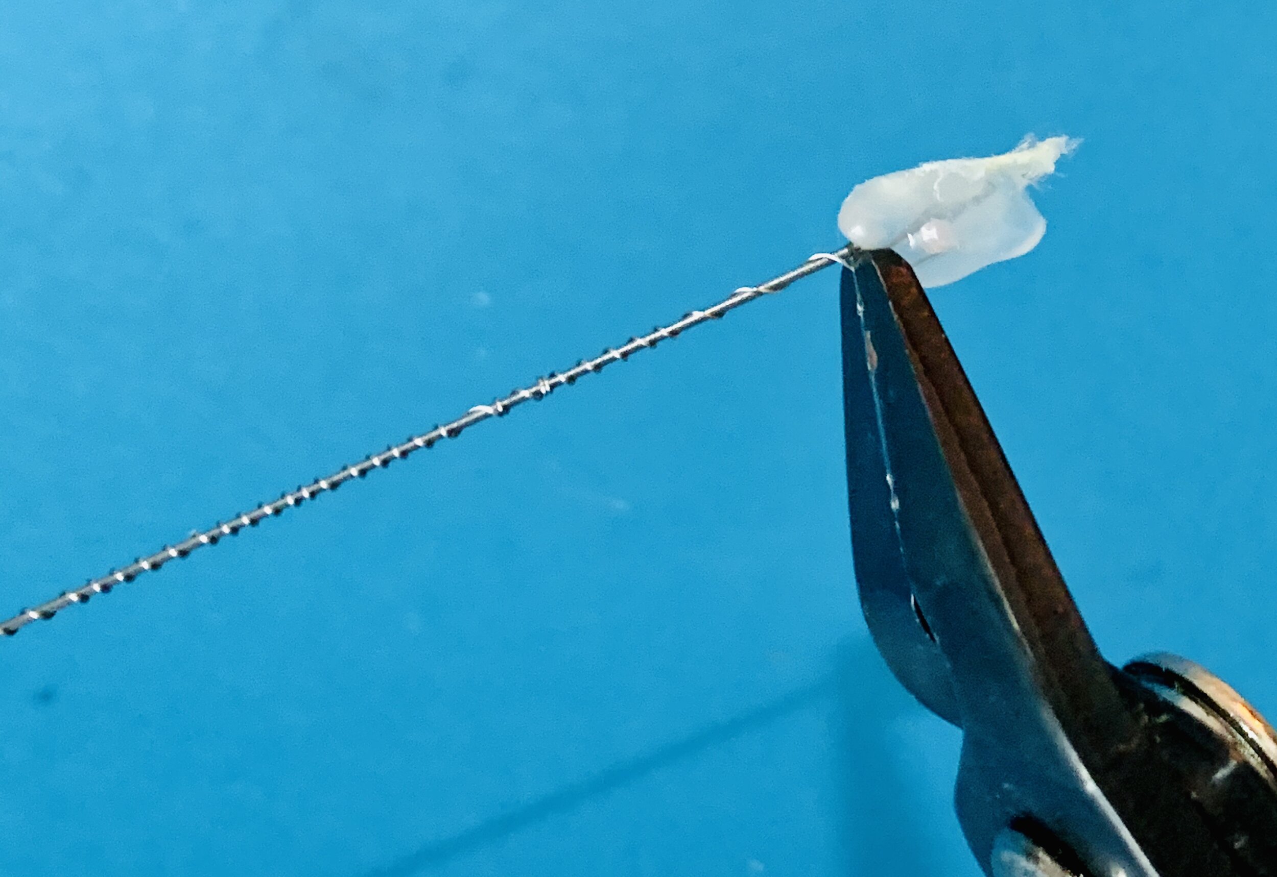
I unspooled about 12” of nichrome, secured the spool using a small vice so it wouldn’t spin, and then the steel wire was secured to the nichrome using a small bead of hot glue.
-
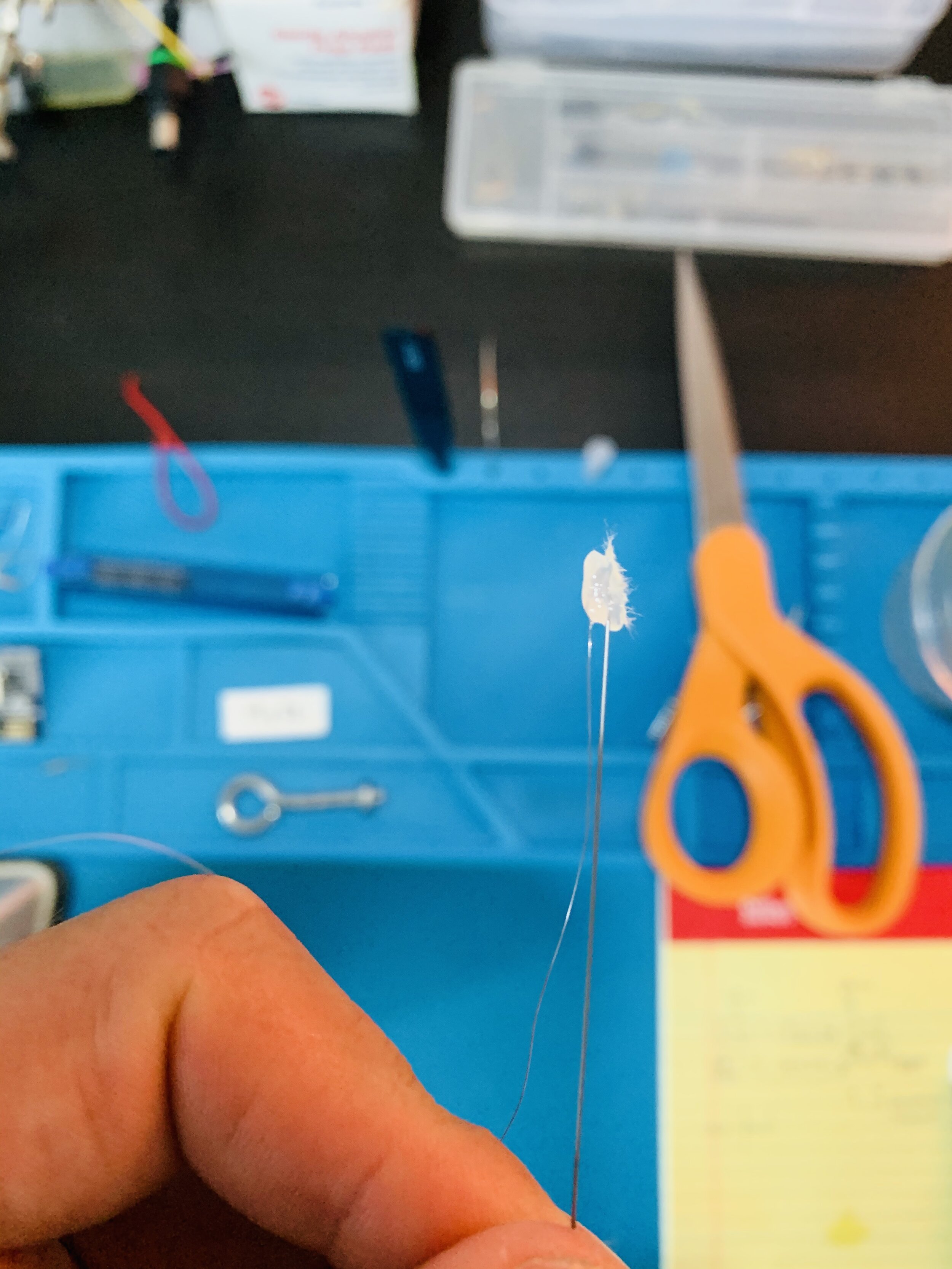
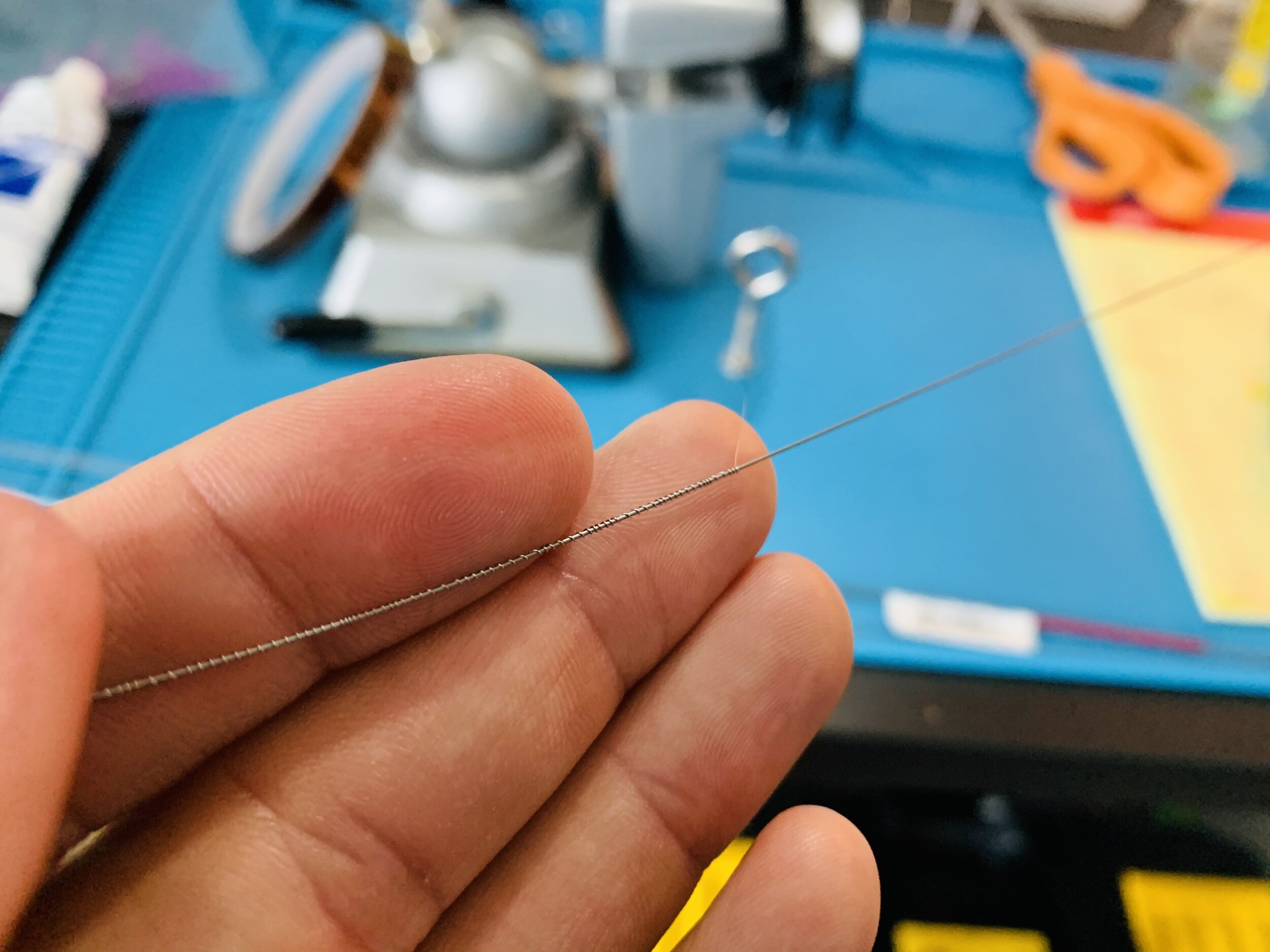
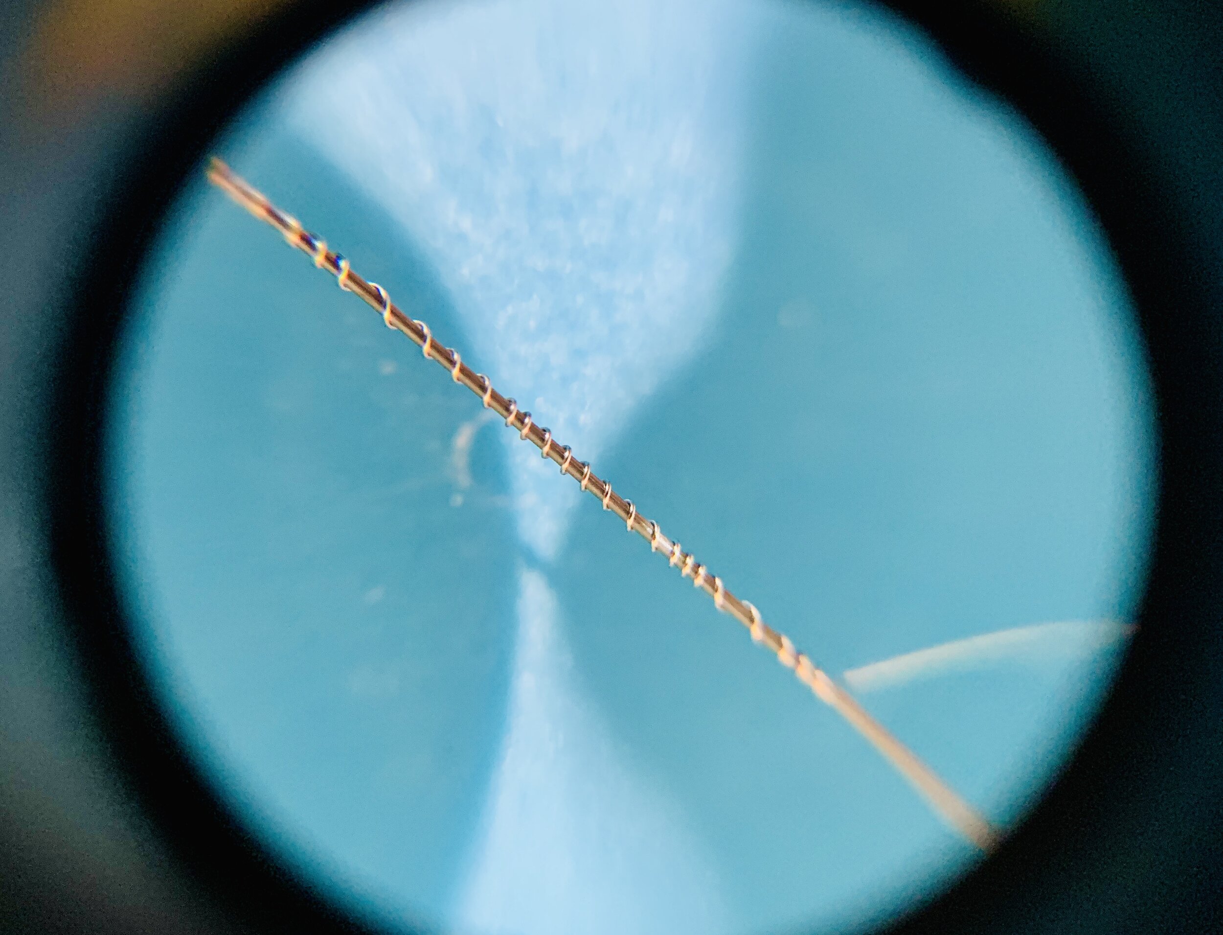
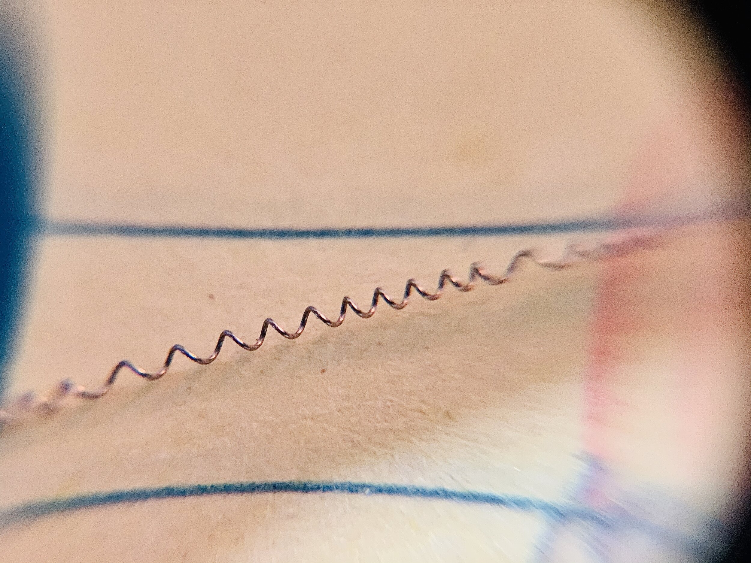
I spun the music wire in my fingers to create the helix. I don’t see any reason why this needs to be super precise, other than keeping in mind you don’t want clumps of wire.
-
The nichrome was then clipped on both ends and slid off the music wire.
-
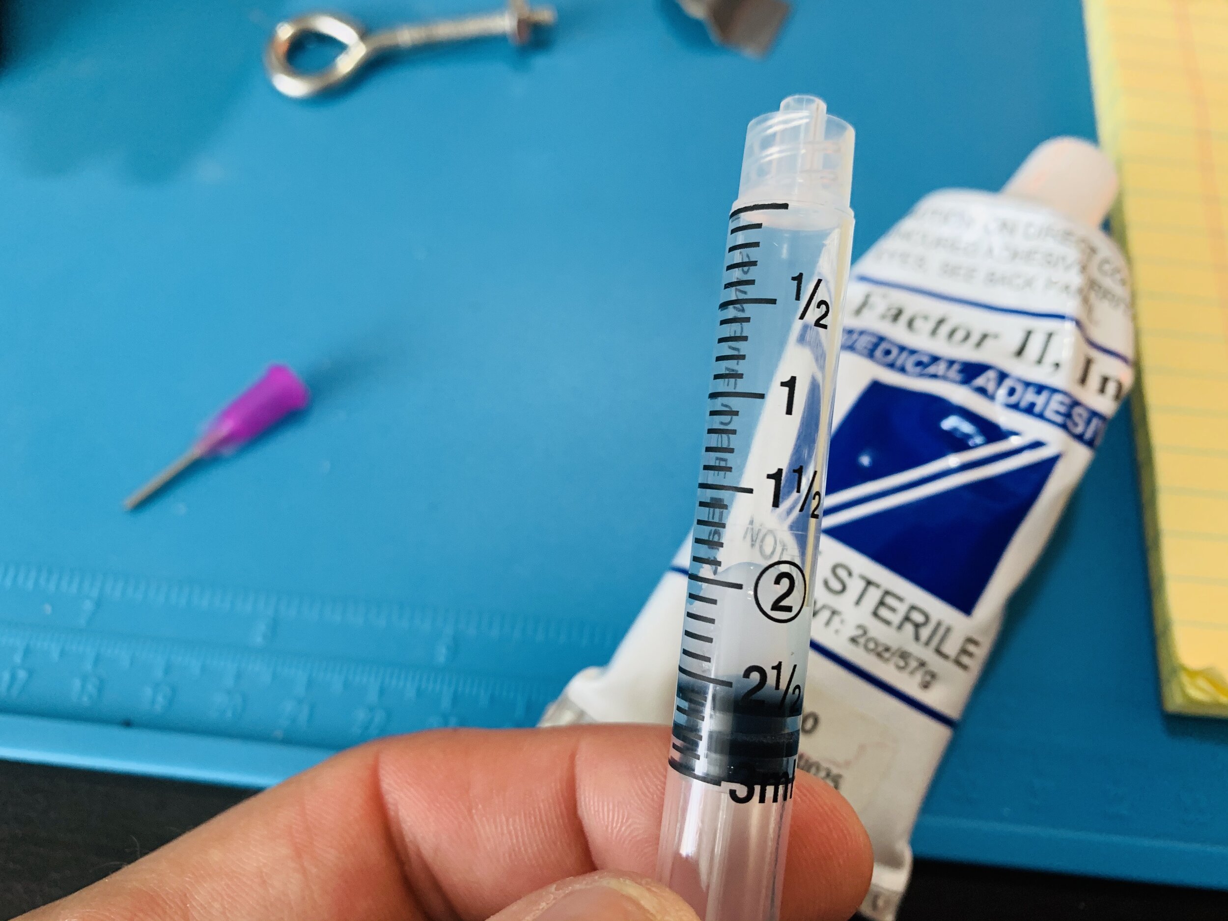
I filled a 3ml syringe with Factor II A-100 medical grade silicone, but I’m sure any silicone will work and this might have been a little thick for this application (see note below about using Vetbond at each end).
-
The helical nichrome was then inserted into translucent heat shrink tubing and plugged using a blunt needle to which the syringe was attached (use a twist lock).
-
The heat shrink tubing was then heated near the blunt needle end which creates a seal by hugging the nichrome.
-
The syringe was then depressed to force the silicone into the tube cavity down about 75% of the nichrome helix electrode.
-
The heat shrink is then held at the needle junction so it doesn’t slide off and and heated towards the open end, compressing onto the wire and forcing the silicone into the remaining 25% of the shrink tube. During this process, you can pull lightly on the heat shrink which will effectively make its diameter smaller and squeeze the nichrome better.
-
After the silicone has encapsulated the nichrome, the needle end is pulled off and the heat shrink is sheared at its end and the helix wire is left hanging upright to set the silicone.
-
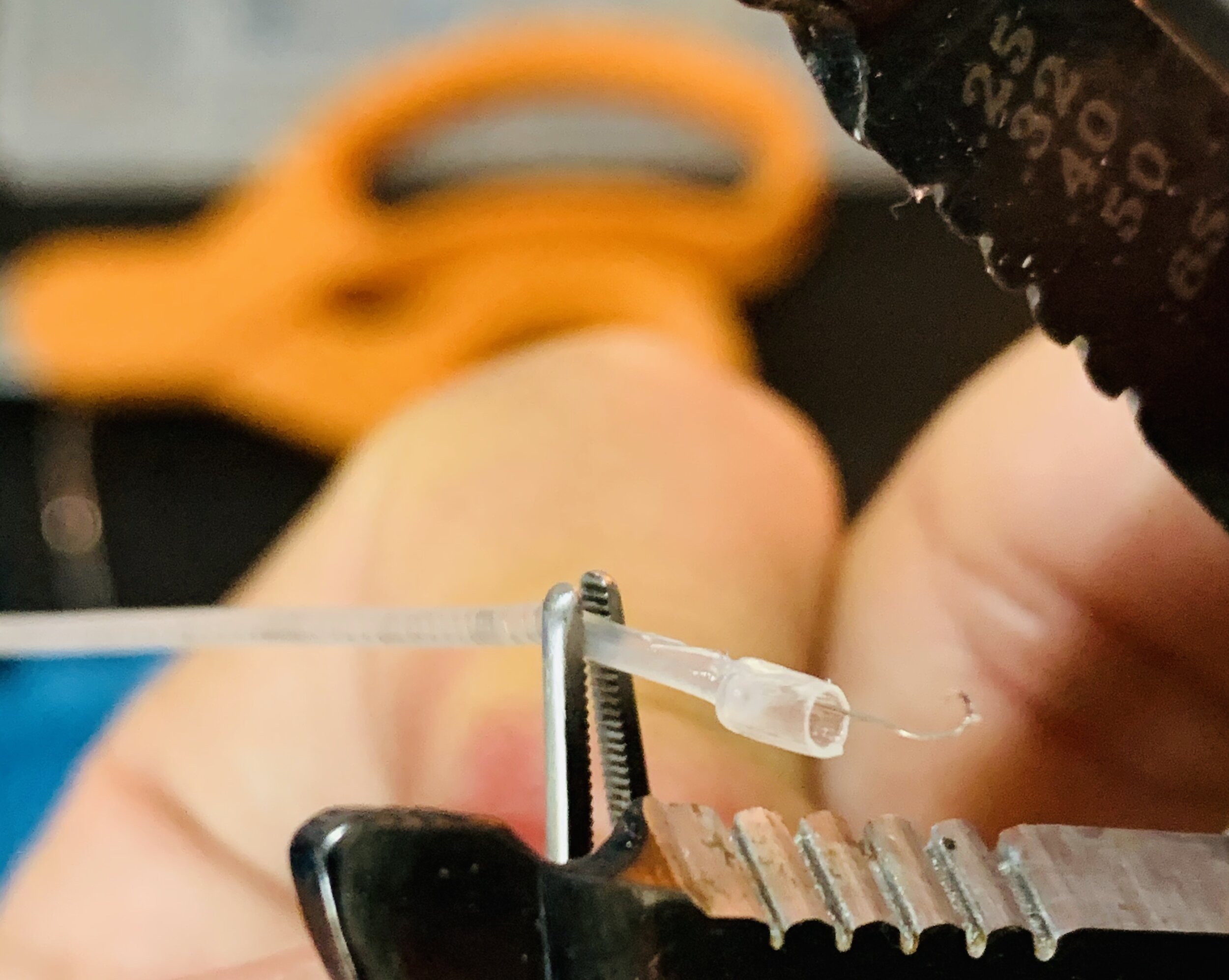
Each end is exposed using small wire strippers that will grab the silicone and heat shrink, but not the nichrome. Gripping forceps or delicate pliers can be used to help hold the helix wire.
Notes
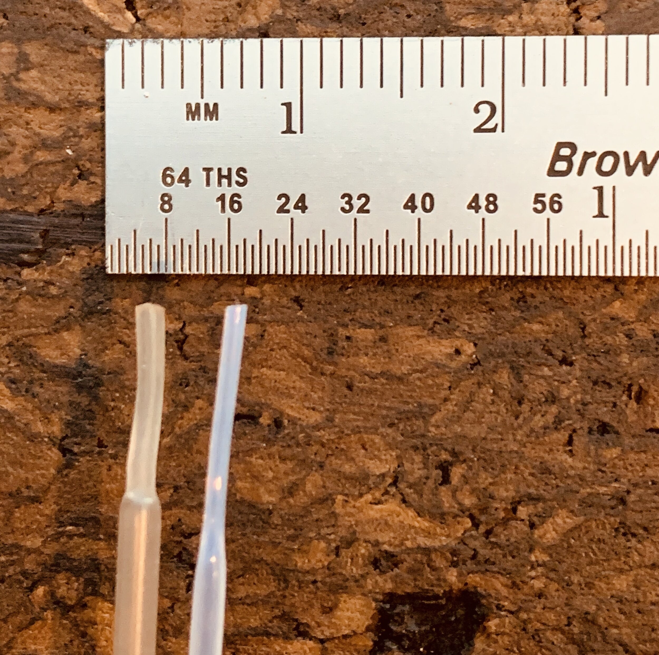
Left: larger, more flexible, low heat requirement. Right: smaller, less flexible, higher heat requirement.
I investigated two alternative configurations: larger wire and smaller heat shrink tubing. 32 gauge nichrome (0.008in, 0.2032mm) is more difficult to twist and adds undesirable rigidity. The smallest heat shrink tubing I could find has a 0.038″ (0.97mm) inner diameter, compared to the 0.046″ (1.17mm) inner diameter of the heat shrink linked in the procedure. The problem is, the smaller heat shrink tubing (photo right) is made of a different, more rigid material, and shrinks at 340°C compared to 90°C of the slightly larger heat shrink tubing (photo left). The higher temperature also causes the silicone to boil and creates air pockets.
Connectorization
The real challenge is interfacing these electrodes because 36 gauge wire is so small and fragile. One reason that I used nichrome was that it can be easily soldered (unlike stainless steel) to connector receptors or PCB pads. Other options would be using silver epoxy or crimping the bare wire.
Sterile Practices
The electrodes in this tutorial are only prototypes. A major practical concern is maintaining the sterility of each material since they all come in contact with the organism. Some tips include:
-
Use a sterile pouch and autoclave the bare wire (removed from the reel)
-
Also, autoclave some gloves for use in the sterile assembly of electrodes
-
Use medical-grade silicone (I haven’t found anything affordable that suggests it is sterile, but some materials like this are inherently innocuous)
-
Soak the tubing in a cold sterilization formula like glutaraldehyde solution like Wavicide-01 before assembly (use a syringe to permeate the inner tube) and then soak the final, assembled device before implanting
In-Practice
As of June 10, 2022, I have implanted many of these electrodes for ~7-day periods with great results. I will note, as with any solid wire, that if the heat shrink tubing is not mounted within a cold acrylic/cement or otherwise fixed, it will shear (when wrapped or pinched by a skull screw). I would offer that it requires a minimum of 0.25” of the heat shrink tube within the cement to stay secured, meaning that posterior skull electrodes can be challenging. My solution is to feed all electrodes anteriorly, collect them with a suture, secure them in that forward position with at least one skull screw, then bend the posterior-bound electrodes 180°; otherwise, those posterior wires will wiggle loose over time and break off.
Electromyogram (EMG)
Most applications require an EMG wire but I am not excited about introducing a suture or shank into the muscle of an animal that is meant to behave normally and survive a surgery. I am currently exploring a method of creating bipolar (two-electrode) EMG side-by-side electrodes.

Proposed EMG Electrode Pair. Two electrodes are cut such that the exposed wires are slightly offset and can not short together. These two wires are held closely together with heat shrink tubing (left). Each electrode has a small portion of wire exposed (~1/8”, right) and folded back with the wire end secured under a piece of heat shrink tubing. This way, the exposed wire is smooth and should gracefully sit over the intended muscle.
