GR/PR: An Open-source Grip Strength Meter

GR/PR on iOS
In animal models of limb disuse, grip strength (or force) is a measure used to characterize the time course and severity of muscle atrophy. For example, in a hindlimb suspension experiment, Morteux et al. (2021) demonstrates significant decreases in max rear paw grip force over 14-days in rats to nearly 50% of baseline. There are several specialized units to measure max grip force in rodents, as well as more general-purpose force meters, but they are expensive and lack modern integration to retrieve the data.
Could I make a grip strength meter (“gripr” or GR/PR) under $50 that solves this problem?
design & Integration
All types of digital scales use some form of load sensor. Rodent grip strength falls into the 0~1000 gram range, such that these low-cost, rigid sensors represent an ideal solution. These load sensors receive a constant voltage input and then output an analog voltage that fluctuates with a load presented orthogonal to the mounting posts. The primary consideration for using these sensors is that the analog voltage can be quite small, such that it requires a good analog-to-digital converter (ADC) to process the signal. External ADC modules are common and cheap, but some microcontrollers very good ADC modules built-in.
The Arduino Nano 33 IoT is built on Microchip’s ARM® Cortex®-M0+ SAMD21 microprocessor that has an internal ADC capable of oversampling the input to a resolution of up to 16-bits, while, importantly, offering a differential input (i.e., between two pins) that is required for the load sensor. The Arduino Nano 33 IoT also has the latest Bluetooth Low Energy (BLE) capabilities that can be easily implemented with the Arduino BLE library.
With these components, the integration scheme is: Load cell → Arduino 33 IoT → iPhone
The Mount & Enclosure

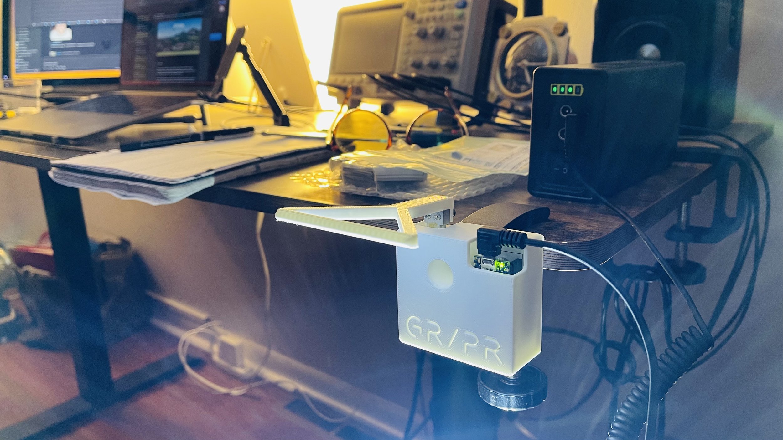
The most straightforward mounting solution is a simple 1/4” bolt/thread that is commonly used for cameras. This offers a range of brackets/mounts, but I chose a C-clamp perfect for a workbench.
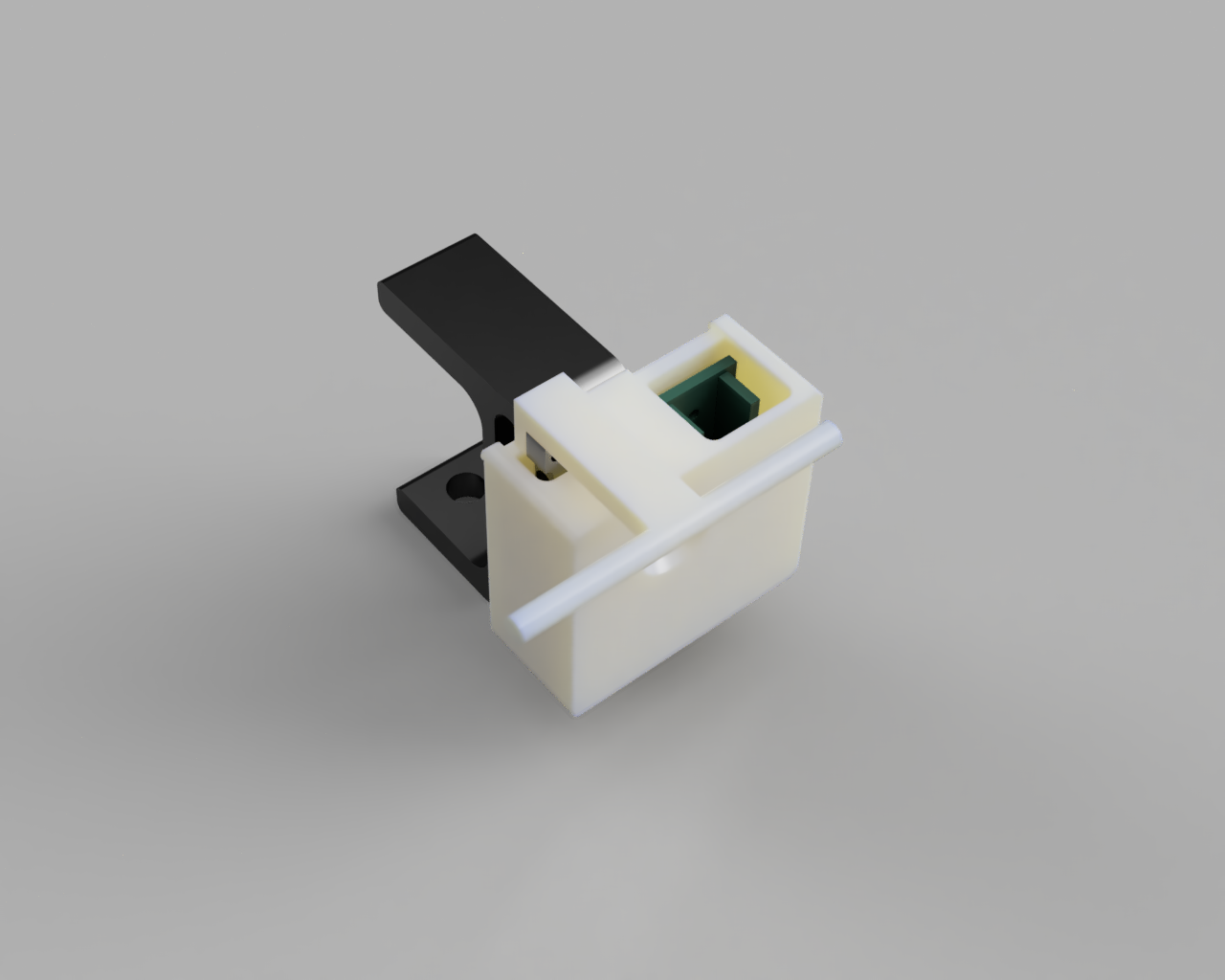
The enclosure was designed to house all the components and secure tightly to the C-clamp. It is comprised of two pieces that click together while the load bar is mounted separately and can easily be modified using Autodesk Fusion 360. It only takes a few hours to print in PLA on a Prusa Mini and assembles with M3 hardware (plus the 1/4” bolt).
The Printed Circuit Board (PCB)

GR/PR PCB
Since the Arduino interfaces directly with the load sensor there are only a few connections: these could be soldered directly, or connected with a breadboard or prototype PCB. However, I wanted to make all the electronics as tidy as possible using a custom PCB that has pins for the Arduino as well as some terminal blocks for the load sensor wires. Plus, PCBs from JLCPCB are so inexpensive ($2 boards, $19 shipping).
Software
Arduino
The Arduino simply samples its internal ADC connected to the load sensor. This is accomplished using a third-party ADC library for the SAMD21 that configures and enables differential measurements and provides the code to select ADC gain and resolution; the standard analogRead() function will not work. The other two pieces of magic concern calibrating the sensor (which requires a little linear algebra) and saving calibration values into non-volatile memory.

GR/PR prototype
The calibration requires that a known load (e.g., 200 grams) be applied and then a function in the form, y = mx + b, is built to readily convert the raw ADC signal into grams. Note: I tested these sensors and indeed, their load-voltage response is linear.
Calibration values are stored in flash memory which is maintained through power cycles unless the Arduino itself is reprogrammed. I used a library for the SAMD21 chipset that emulates EEPROM. I have yet to determine if these calibration values can be hardcoded but I assume these low-cost load sensors have some variability and will require a one-time calibration.
The Arduino is programmed to spit out calibrated load values through the serial port if iOS is unavailable, but it does not, itself, do the work of identifying max load values. However, these could be extracted from the Arduino IDE Serial Plotter.

Arduino IDE Serial Plotter
ios (iPhone) & BLE
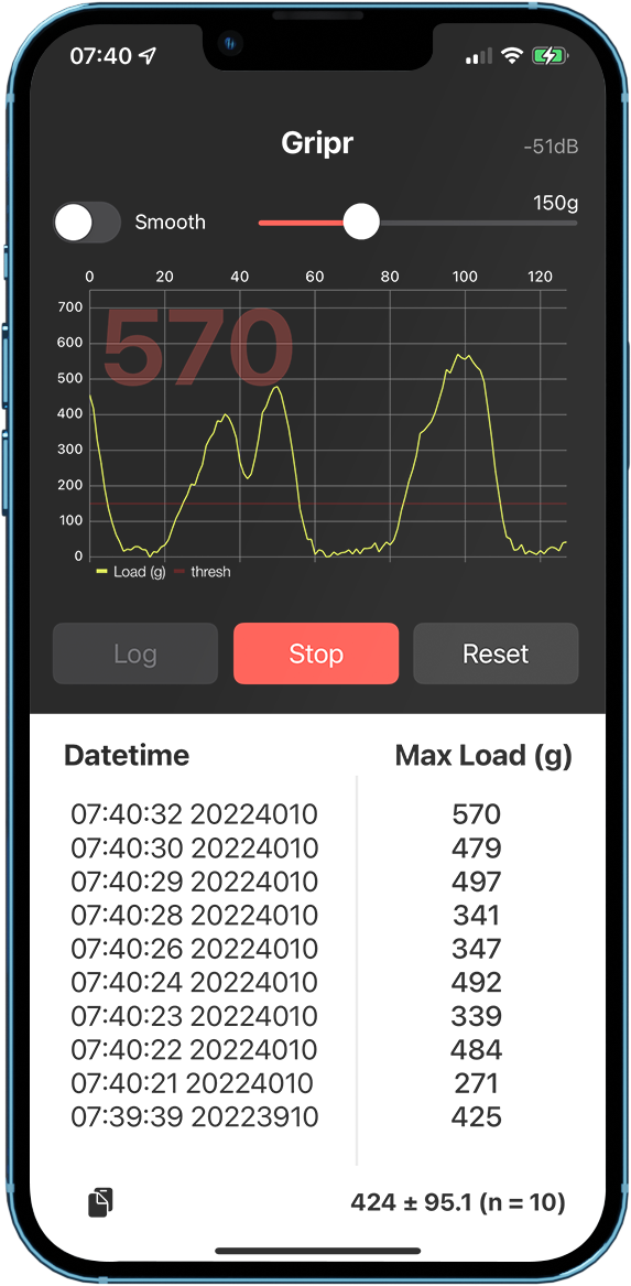
GR/PR iOS app
The Arduino has one BLE service and a single characteristic for the load data. Architecturally, this allows the “central” BLE device (iPhone) to decide what to do with the data instead of trying to conform to something programmed into the Arduino. The load data are sent in Int32 (4-bytes) packets using BLE notifications.
The GR/PR app is designed to monitor the load data, display it, and create a log of max grip strength measures. Once the Arduino is connected, the data is plotted and a threshold can be set for logging. After starting the log, when the load exceeds the threshold the program begins tracking the maximum load until the load goes back below the threshold—this ends a trial. The log will accrue trials automatically and provide a mean and standard deviation for the collected data. The log data can be copied to the iPhone clipboard (lower-left) in CSV form for archiving.
Conclusion
There are quite a few barriers to entry in this project, one being that the GR/PR app is being deployed using my personal iOS developer account. But with a 3D printer already in-house and the essentials for electronics fab, the total part cost was down in the $50 range. The initial prototype took about 3 days (~20 hours) to build. It would be great to see if anyone in the medical/science community is thinking about limb disuse or fractional gravity and its impact on mammalian physiology (e.g., exposure to space).
In an effort to move towards an accessible grip strength meter and other projects requiring load sensing, here are all the links to the parts and software for GR/PR:
