A Dynamic Hindlimb Unloading Apparatus
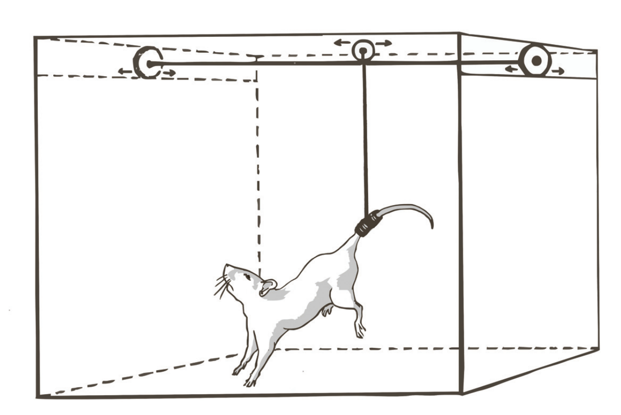
Hindlimb Unloading Model of Microgravity (see Gnyubkin and Vico, 2015).

Load on Forelimbs (left, black) and Tension on Tail (right, red) versus Angle of Head-down Tilt. Equations are my own, dotted lines are best fit (recreated from Hargens et al., 1985).
Introduction
The hindlimb unloading (HU) model has been used to simulate microgravity—and more broadly, disuse—for over 40 years (E. Morey-Holton et al., 2005; E. R. Morey-Holton & Globus, 2002). Since the National Aeronautics and Space Administration (NASA) confirmed similar tissue fluid shifts and musculoskeletal responses in rodents compared to subjects in the weightlessness of space, HU has become an important model to study other physiologic factors relating to metabolic, endocrine, and adrenal function. However, the current (and common) HU apparatus is statically calibrated, such that the hind-limbs are unloaded through tail suspension using a constant force. This weight is typically equal to a 30° incline (i.e. head-tilt down) which matches the cephalic fluid shift and pressures experienced in zero-G (Hargens et al., 1985) while providing normal weight-bearing on the forelimbs and unloading the lumbar vertebrae but not the cervical vertebrae. Since tilt-angle and weight-unloaded are co-linear, the notion that a standard unloading protocol could be implemented dynamically is possible if the unloaded weight could be monitored. A dynamic HU apparatus would allow real-time modulation of fluid shifts and thereby enable investigation of acute, temporally-precise investigation of physiology and neural activity. Here, I explore the design of a dynamic HU apparatus using a calibrated and closed-loop load cell fed-back to a motor controlling the hind-limb unloaded weight. Coordinated neural recordings may make possible first-of-their-kind, causative demonstrations of microgravity-induced neural adaptations.
Other Reading
-
An Alternant Method to the Traditional NASA Hindlimb Unloading Model in Mice (Ferreira et al., 2011)
Design Concept
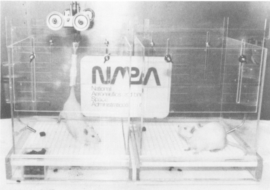
Early Hindlimb Unloading Cage (see Wronski & Morey-Holton, 1987)
The most common HU design augments a rodent home cage with a low-friction, X-Y-style track to allow free movement. This design requires that animals be weighed using a special balance that unloads animals to the same degree as the cage. Issues with this design include the possible use of nest material built to reduce the intended hindlimb load and cumbersome re-calibration of the unloaded weight.
If hindlimb load is constantly being measured, a dynamic loading system removes the need for the X-Y track. To perform load measurements, a load cell can be used that utilizes an internal Wheatstone bridge to translate physical deflection into differential voltage. This type of load cell is typically used for scales; they are a rigid aluminum-alloy with an IP65 rating (“dust tight” and water-resistant) and can measure grams to kilograms.
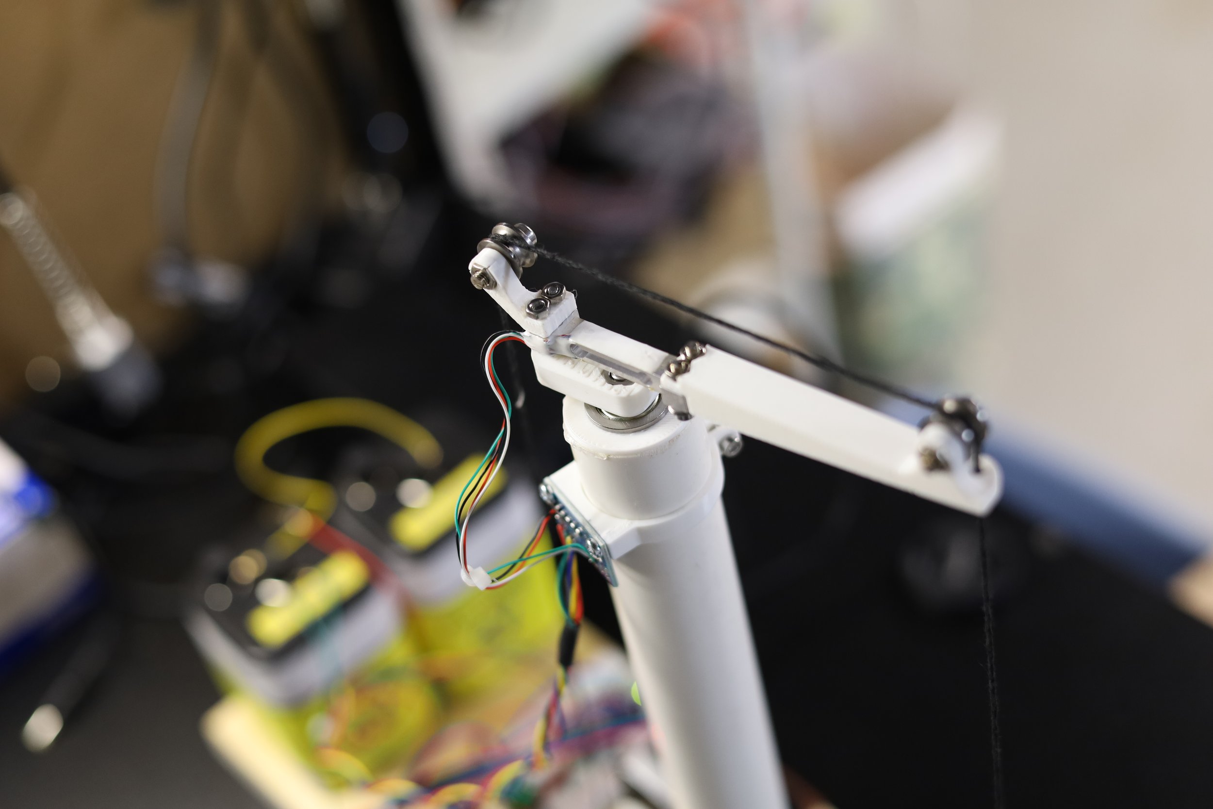
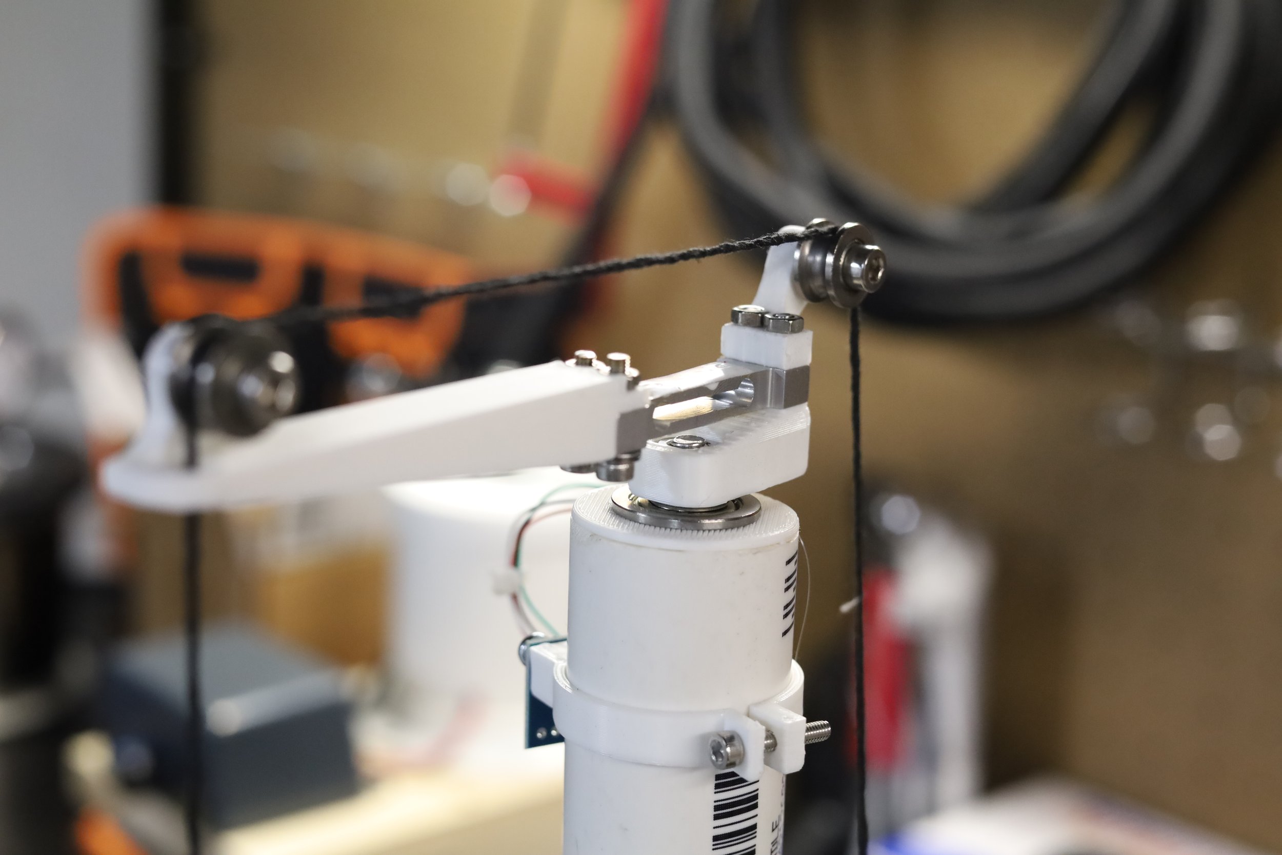
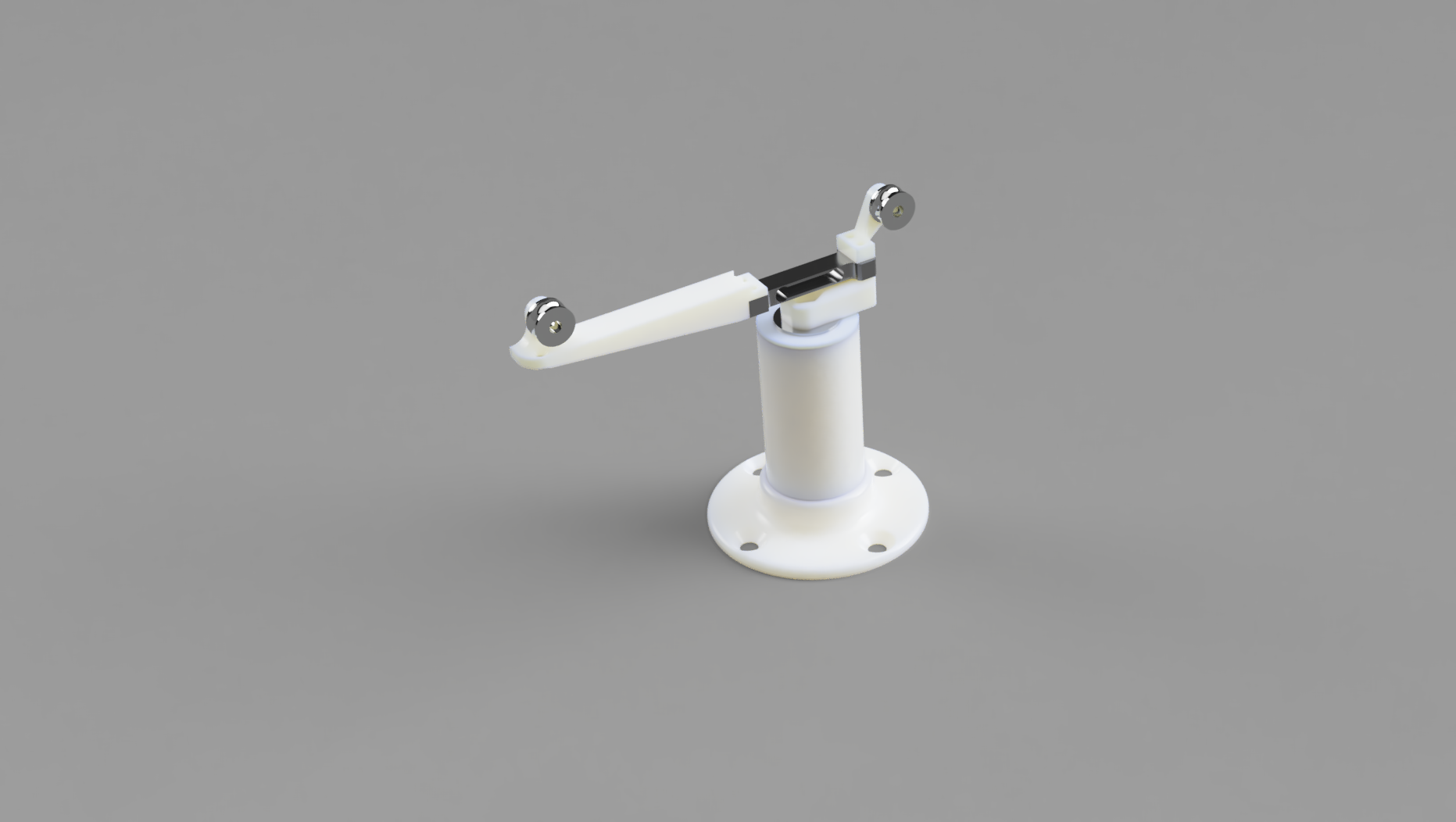
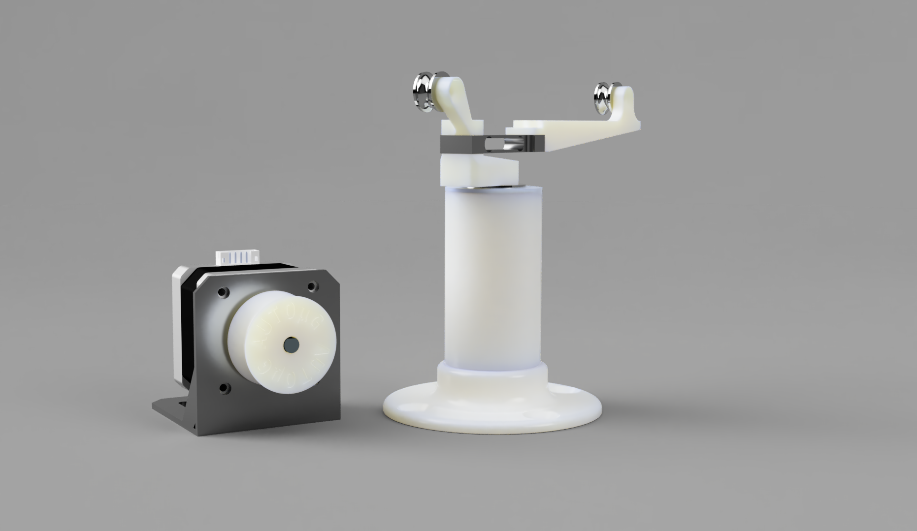
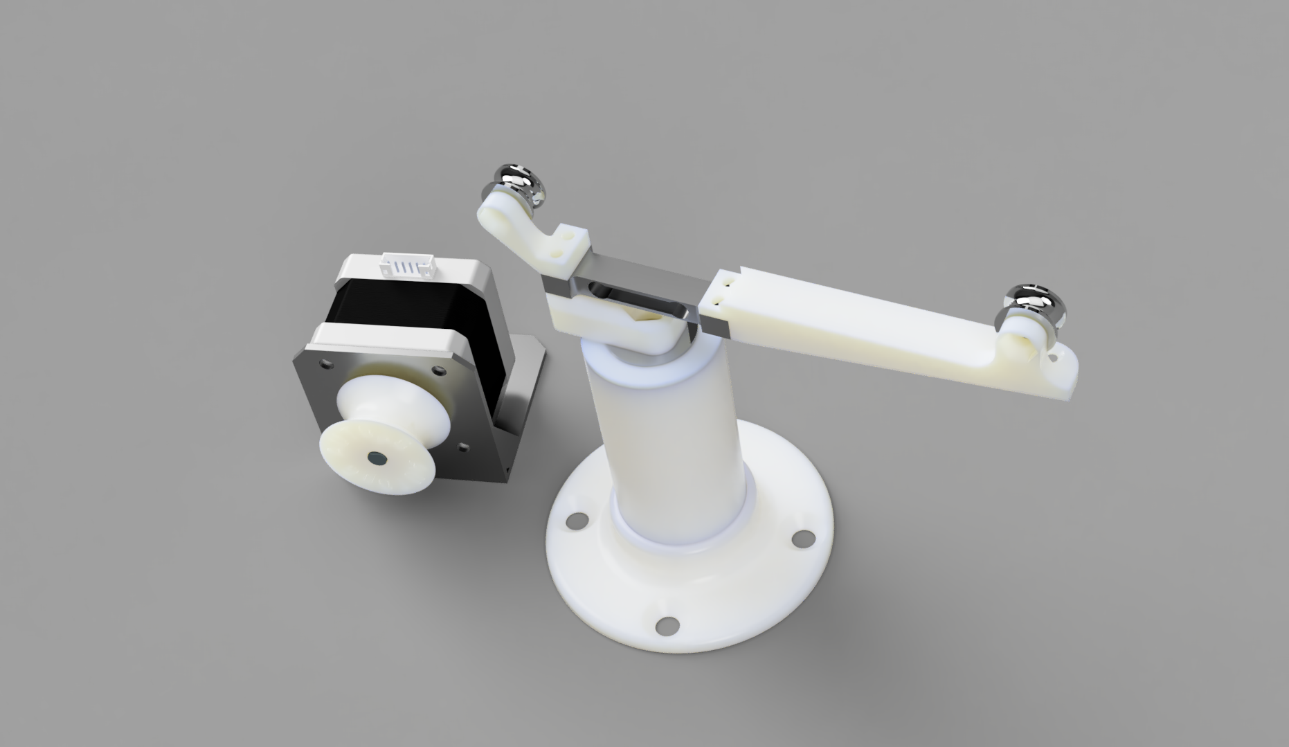
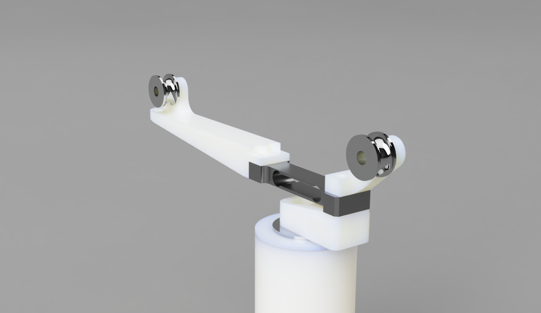
Mechanics
This concept is based on a swiveling crane where the load is measured via the load cell which makes a beam through the swiveling arm. The height is set by a standard 1” PVC tube which uses a flange bearing to achieve the swiveling action. A tensioned line runs from a ground-mounted stepper motor through two frictionless pulleys and is finally guided through a single through-hole into the space (or cage) below. The custom parts shown can be 3D printed in roughly 90 minutes using PLA material and are assembled using standard metric hardware (see BOM below). Parts were designed and rendered in Fusion 360, sliced in Prusa Slicer, and printed on a Prusa Mini.
Control System
Load bearing is continuously sampled from an Arduino Every Nano connected to an ADS1115 differential ADC module communicating over I2C. The control of a NEMA 17 motor is accomplished through a 4-wire stepper motor library and external stepper motor controller (prototype code on Github). The system works in the same manner as a thermostat: the motor keeps constant tension on the unloading line with some error to eliminate feedback oscillations.